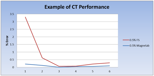
Accuracy/Tolerance Explanations:
A question is often asked about what the difference is between the tolerances specified by Magnelab and other companies. Don’t be deceived by the numbers or catch phases, know what you are getting when ordering current transformers (CT’s). When looking at the specifications for a CT, the accuracy rating or class can be depicted in many ways. In order to insure the correct CT is chosen for a given application it’s important to know what the specifications are stating, or not stating. Below are examples of tolerances and ratings you may see where “X” represents the accuracy:
X% at 10% to 130% of rated current – When the tolerance and range are specified the CT can be considered to be accurate to the specified tolerance across the entire specified range.
X% at rated current – The tolerance is only effective at the specified current and not over any range of currents.
X% FS – “FS” stands for “Full Scale” and again the tolerance is only effective at the specified current and not over any range of currents.
X% Dynamic Range – This means it will meet the specified tolerance over the usable range, but if the range is not specified this rating is vague at best.
Revenue Grade – The term “Revenue Grade” is used fairly loosely in many instances. If this statement is made with no reference to the standard the unit is tested against then there is no guarantee it will meet the true ANSI, IEC, IEEE and/or CSA standards for revenue grade. For a unit to be truly “Revenue Grade” the ANSI, IEC, IEEE and/or CSA standard must be stated along with the accuracy class. For example a part specified as “IEC 61869 accuracy Class 0.5” should meet the standard for 0.5% accuracy based on the test requirements of the IEC 61869 standard. If this detail is not given, the term “Revenue Grade” is meaningless.
All of these accuracy specifications are used primarily when stating linearity accuracy. However, it’s also important to specify the phase shift tolerances as well. Phase shift tolerances must also be properly delineated using the same criteria as the linearity replacing the “X%” with “X°”. When a CT is tested for over-all accuracy, both the linearity and phase shift tolerances must be considered.
If there is ever a question, it’s always better to ask the manufacturer to clarify or elaborate on the accuracy specifications of the unit rather than assume what you are getting will meet your requirements.
Eric Christensen
Magnelab, Inc.
Director of Engineering and Sales
Topics: Insider, Products


How would you optimize using a current transformer to detect very low voltages and currents such as in a guitar pickup? I did some research on this matter and would like to hear your input. Web search ” Low Impedance Pickup Research” to see what I have posted on the Music Electronics Forum. There is a lot of world wide interest about this topic.
I am targeting the input impedance of a typical XLR microphone mixer input which is typically 2400 ohms (actual) designed to be a bridging impedance for a microphone rated at 150 ohms but can range up to about 250 ohms.
By using a Triad CSE187L current transformer (CT) and extending the single loop primary about 2.5 inches to span the width of 6 guitar strings and placing a magnet in the center, I can produce about 5 to 10 mV output level. My later research uses a Triad CSE186L that has three turns of AWG 16 wire for the primary, I remove that winding to have a primary opening of about 0.156 inches square opening to accommodate a thick round or square wire to increase the primary current and ultimately the secondary output voltage. With this technique I only need to make one primary low resistance primary coil loop joint to ensure the lowest resistance primary and string loop resistance to maximize the current.
My ear tells me that the skin effect has an influence on the low to high frequency balance when I use very thick wire to make a primary transformer and string loop.
Right now I am considering requesting a custom three layer bobbin with the primary CT turn in the center layer with a secondary coil located on each side of the primary to reduce leakage inductance and provide a variety of turn ratio outputs with either a series or parallel connection of the two secondary coils that are center tapped or tapped at a point to make pleasant sound changes into the typical microphone mixer input impedance.
I would appreciate any input or technical areas to look into to further my research.
Thanks.
Joseph J. Rogowski